Senior Design Project 2023
Multifunction CNC Machine
Progress Log
Week 28, Nov 18 - 25
Team:
For this week and the final week of semester, we finalize the Multifunction CNC Machine operational and its capability to have an accurate and ready-to-go machine. We worked on a PowerPoint presentation as well as the final project report paper to meet the due date for submision.
Week 27, Nov 11 - 18
Team:
The team's focus was to continue troubleshooting the machine for its final performance. We worked on editing and made changes to the final report paper to submit within the deadline due date.
Week 26, Nov 4 - 11
Ramon:
During this week, my primary focus was predominantly on refining and enhancing the project report, dedicated substantial effort to correcting errors, ensuring clarity, and aligning the content with the specified rubric. This meticulous approach aimed at presenting a comprehensive and well-organized document that effectively communicates the details of our project.
Simultaneously, continued our work on the machine, concentrating on adjustments and calibrations. This dual focus allowed us to maintain a balance between documentation and practical aspects, ensuring that both the report and the machine's functionality received the necessary attention and refinement.
Yohanes:
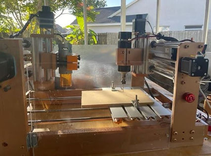
Throughout this week, the goal was primary centered on the machine, especially engaged in the construction of the enclosure, ensuring a secure environment when the machine is operating.
The safety enclosure, a pivotal component, is equipped with an alarm system. This serves as a crucial safety measure should the machine door open during operation; the alarm activates persistently until manually reset or the door is securely closed. This additional safety layer ensures a secure working environment and underscores our commitment to prioritizing safety throughout the project.
Parallelly, conducted extensive laser operation tests, employing diverse software tools to optimize the machine's performance.
Team:
This week, as a team, we dedicated our efforts to further refining the CNC machine. We conducted multiple adjustments, focusing on calibration and performing thorough functional tests, particularly on the laser spindle. Simultaneously, we diligently worked on the project report, addressing errors, and incorporating additional content to enhance its overall quality. Additionally, we dedicated time to improve the website, implementing changes and ensuring the entire website is up-to-date with the latest information.
Week 25, Oct 24 - 31
Ramon:
This week I continued writing and editing the project report paper and the PowerPoint presentation. Also, did a little practice with some software design "Easel" and its gcode to be uploaded to the CNC Machine. For the most part, this week was all about documentation reports and research.
Yohanes:
Throughout the project, dedicated significant time to troubleshooting various issues that arose during the machine calibration process. This involved meticulously identifying problems, conducting in-depth research to understand the root causes, and implementing effective solutions. Performed extensive testing procedures, meticulously examining every aspect of the machine's functionality to pinpoint areas of improvement.
In addition to troubleshooting, focused on enhancing the carving capabilities of the machine. This meant experimenting with different carving techniques, tool configurations, and materials to achieve optimal results.
Simultaneously, we undertook the task of rewiring the machine. This intricate process required a keen eye for detail and expertise in electrical systems. By rewiring components, we aimed to enhance the overall efficiency and reliability of the machine's operations. Careful attention was paid to every connection and circuit, ensuring seamless communication between different parts of the machine.
Team:
This week, we continued working on machine calibration and product quality. The machine is running as it should, but when testing the carving on different blanks, it is not working properly. We started troubleshooting the machine itself, and it is operating correctly electrically. All voltage and current values are reading correctly. The main problem is with cutting. We researched cutting materials and cutting tools and identified two main types of cuts for CNC machines: up-cut and down-cut machining. The choice between these techniques depends on several factors, including the type of material being used and the desired outcome of the project.
For up-cut CNC machining, also known as conventional milling, the cutting tool rotates in the opposite direction, moving against the workpiece and creating chips as it cuts. This method is suitable for soft wood and plastics. On the other hand, hard wood, metals, and hard composites require down-cut machining.
Apart from the cutting type, the type of cutters used is another crucial factor we examined, which caused issues in operating the machine. There are four different types of cutting tools to choose from, depending on the material and speed.
Despite calibrating and adjusting the CNC machine, the results were still unsatisfactory. During continued troubleshooting, we discovered that the Z-axis motor was weak and unable to cut the blanks deeply. Upon testing the motor multiple times, we found that its output power was very low. When tested independently, the motor exhibited noise and sluggishness during startup. Consequently, we have placed an order for a new motor with similar specifications to address this issue.


Week 24, Oct 17 - 26
Ramon:
Last week the CNC Machine was presented and the project implementation was a success, all components were fully operational. For this week I focus on editing the project report and adding updated information. Also updated the website as well as continued working on the CNC Machine software and performed more system run tests. More modifications are to come as this project comes close to ending the deadline to be presented. A video of the entire model system can be viewed on our YouTube channel.
Yohanes:
We encountered issues while working with our engraving and leatherwork machines due to the limitations of the software we were using. The access provided by our current machine software was extremely restricted, causing problems in the engraving and leatherwork processes. To address this challenge, this week exploring different software options. After thorough testing, we found that Easel worked exceptionally well for engraving tasks, while CorelDraw proved to be highly effective for leatherwork projects.
took the initiative to download both Easel and CorelDraw and dedicated time to self-train on these platforms to enhance my proficiency. Through diligent practice and learning, have gained the necessary skills to perform a wide range of tasks efficiently. Now, we are confident in my abilities and capable of accomplishing various tasks in both engraving and leatherwork, thanks to my proficiency with these software programs.
Team:
Continuing our efforts to enhance the machine's performance, we delved deeper into the intricacies of its operations, making meticulous adjustments to improve the product quality. Throughout our continuous testing and troubleshooting process, we identified a recurring issue - the limitations posed by our existing software. In response, we embarked on extensive research, exploring a multitude of software options available in the market.
After thorough evaluation and experimentation, we narrowed down our choices to two exceptional software solutions: Easel, which proved to be incredibly effective for engraving tasks, and CorelDraw, specifically tailored for laser applications. Embracing these software platforms marked a significant turning point for us. Easel excelled in delivering intricate engraving designs, while CorelDraw showcased its prowess in precision laser work.
These software options apart are their flexibility. They not only allowed us to upload existing models but also provided customization capabilities. This newfound flexibility empowered us to tailor designs according to our specific requirements, enabling us to create and produce a wide array of products.

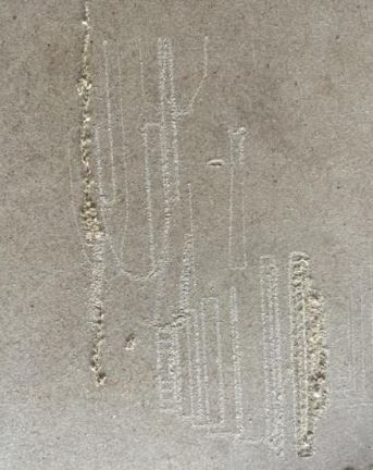
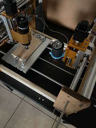
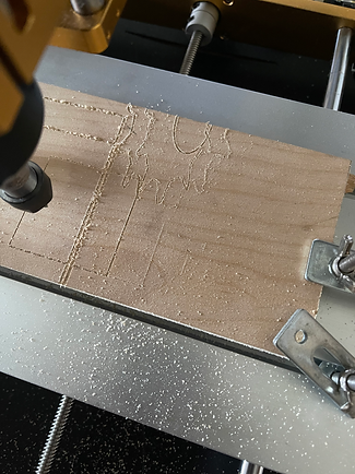
This image of a puma has been meticulously designed and traced using Easel, rendering it ready for the engraving process. With careful attention to detail and precision, the intricate features of the puma have been captured and translated into a digital format within the Easel software. This digital representation is now primed for engraving, ensuring that the final product will showcase the fine craftsmanship and accuracy that Easel facilitates.

This picture illustrates the translation of the above model into the cutting process. The blue lines indicate precisely where the material will be cut, providing a clear visual guide for the fabrication process. These meticulously marked lines serve as a roadmap, ensuring accuracy and precision during the cutting phase.


Week 23, Oct 10 - 17
Team:
The team met for two consecutive days and worked on the project to calibrate and troubleshoot the system for the Oct 17 deadline and demonstrate the full operation of the CNC Machine. We adjusted the system body frame and made it stabilize, tested all component parts to ensure they were all fully functional and operational for a final troubleshooting performance. Also painted the model for a better presentable view.
The team met on October 9, 2023, at 9 am to work on the project. First, adjustments were made to the machine body. The machine's framework supporters and tables were measured for their squareness using a level and angle iron. Any issues found were corrected, and the components were bolted permanently. The machine was then run and checked for vibrations or unnecessary movement, and all issues were eliminated.
Next, calibration was performed. Once the machine was permanently adjusted, each axis movement was operated one by one for calibrations. Problems were identified with some axis movements towards the ends, and troubleshooting revealed non-uniform gaps. These gaps were adjusted, and the machine was operated multiple times. While major issues were resolved, some problems persisted, particularly with Z-axis #2. The problem was identified: the motor screw holes were irregular, causing wobbly movements. This irregularity made the laser machine operate improperly.
A new design solution was devised: a shim with correct holes was created using a 3D printer. The motor was bolted onto the shim, and then the shim was attached to the machine. This eliminated the motor wobbling. After all these adjustments and modifications were made, the machine was operated multiple times for testing, and it is now functioning without any issues.
On October 10, 2023, the team gathered for the second day of work on the project. Initially, we checked the machine's overall stability and conducted functional tests to confirm that the adjustments made on October 9, 2023, were still effective. Indeed, the machine was in great condition.
Next, we focused on the machine's appearance. Different parts of the machine came with different colors, and it was crucial for the bare wood to be uniformly painted for weather protection. We meticulously checked each part for cracks and dents, finding no major issues. Small holes were filled with filler, sanded smoothly.
To safeguard all electrical components, wires, LED screws, rods, and any moving mechanisms, we wrapped them thoroughly with tape and paper. With the appropriate personal protective equipment (PPE) in place, we applied primer paint to cover any remaining defects. Subsequently, we applied the copper-textured color twice. The accompanying pictures illustrate the painting process and the final result.
Ramon:
I created a channel to show videos of our project progress. All videos posted are currently as of now, they show the CNC Machine with test run and adjustments such as engraving pattern design on a board and the laser making a burn design onto a board. For in-depth of the project's progress and to view the video please click on the YouTube link mentioned at the beginning of the paragraph. Also, this week worked on the draft report paper and website and made adjustments based on the suggested meeting.
Yohanes:
Throughout this week, Ramon and I made significant strides in our efforts to make the system fully operational. One of my key tasks was gathering all project documentation, a crucial step to enhance the visibility of our project progress log on our YouTube channel. By compiling comprehensive documentation, we aimed to provide a clear and transparent view of the project's development process to our audience. This included organizing technical specifications, design diagrams, and progress reports into coherent files, ensuring that viewers could follow our projects properly.
Simultaneously, my focus remained on editing paper reports and refining the content on our project website, addressing the suggestions and feedback provided during our team meetings. This involved carefully reviewing the written material, correcting errors, improving clarity, and ensuring that the information presented was accurate and engaging. By dedicating time to these tasks, we aimed to create polished and professional documentation that accurately represented our project's goals, achievements, and ongoing developments.
In summary, our collaborative efforts this week involved meticulous organization of project documentation for our YouTube channel and continuous refinement of paper reports and website content.
Week 22, Oct 3- 10
Team:
The team worked on the spindle motor body frame and uploaded a system design cutting test as shown below. We are undergoing extreme modification so it can be fully operated and meet the deadline to show the completion of this Multifunction CNC Machine. Testing the E-Stop functions and trouble shooting on the machine
Ramon: Worked on the report, updated the website and practicing on the machine for production quality
In addition to these responsibilities, I spent considerable time practicing on the machine to enhance production quality. This involved experimenting with different settings, mastering various techniques, and troubleshooting any issues that arose during the production process. By dedicating time to hands-on practice, I aimed to refine my skills and improve the overall efficiency and precision of the machine's operations.
Yohanes:
During this period, I dedicated my time to various tasks. One of the key focuses was working diligently on the report, ensuring that it was comprehensive, accurate, and well-organized. This involved conducting in-depth research, analyzing data, and crafting clear explanations to convey the intended message effectively.
Simultaneously, I took on the responsibility of updating the website. This task required me to incorporate new content, enhance the user interface, and ensure that the website was user-friendly and visually appealing. I also worked on optimizing the website for search engines, improving its accessibility and overall performance.
Week 21, Sept 26 - Oct 3
Team:
The team worked on the spindle motor body frame and uploaded a system design cutting test as shown below. We are undergoing extreme modification so it can be fully operated and meet the deadline to show the completion of this Multifunction CNC Machine.
Ramon:
For this week the CNC Machine system was tested and troubleshooted with some simple gcode commands to observe its operational function. Some adjustment to the body frame was made for the spindle motor that is mounted on the z-axis such as the measurements from the working bench bed and the spindle motor drill bit to make contact for a cutting design. Also, the frame holding the laser module was worked and built to establish a test laser engraver which is in progress throughout the upcoming week as the deadline for project completion. Below is a video and image of the project's progress.
Yohanes:


This week, activity focused on tasks outlined last week's action plan. Editing the report, adding relevant captions, and providing detailed explanations for the included pictures. Additionally, conducted research and composed content about G-code openness. Furthermore, wrote a lesser learn issue, about the lessons learned from G-code and AutoCAD programming, ensuring a comprehensive understanding of the subject matter.
Week 20, Sept 19 - 26
Team:
As a team, we discussed the previous week's agenda and the professor's suggestions, which involved working on Chapter 3. Following the professor's advice, instead of having a separate chapter document, we integrated Chapter 3 into the entire report and updated the report format to incorporate this change. Furthermore, we discussed and documented the process of building the subsystems, which we added to Chapter 3.
In addition to updating the website's implementation, we focused on the CNC machine, making necessary adjustments and addressing any lingering issues from our previous work.
Ramon:
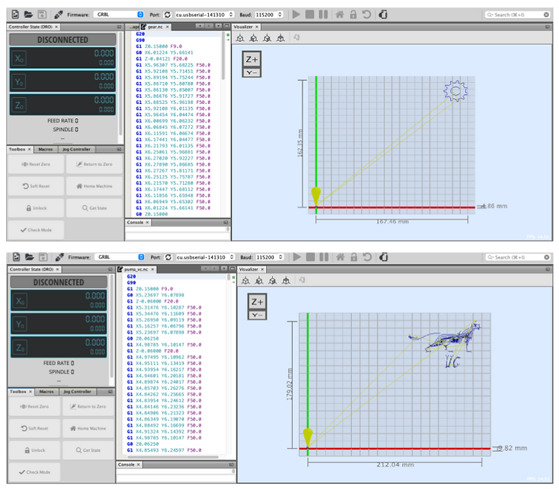
Throughout the week the CNC Machine project has been undergoing some test runs, troubleshooting, and modification. The machine is equipped with two microcontrollers that enable the stepper motor and the spindle/laser modules, which were constantly tested to ensure they operated while uploading the given gcode commands. At this time the body frame needs some adjustments that are been addressed such as calibration and stability. The below images are some design patterns that I currently was practicing and getting more in-depth with gcode and Universal GCode Sender (UGS). Continue editing website and paper report.
Yohanes:
Carefully reviewed the project design report and assembled detailed insights into how we construct and assemble the subsystems, providing a thorough explanation from raw materials to the final subsystem components. Moreover, I've conducted rigorous inspections and made precise adjustments to enhance the stability and calibration of the CNC machine, guaranteeing the smooth operation of all components. Attached, images for visual explanation. Currently, the project is in the proposal phase, with ongoing test runs aimed at ensuring its readiness for operational.


Week 19, Sept 12 - 19
Yohanes:
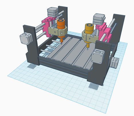
Reassembled all the component parts for CNC, and performed a functional test on the first spindle, and it is working correctly. Afterward, I completed the second z-axis assembly and finished assembling the frame. However, there are still some modifications that need to be made to fully complete the CNC Machine body frame. The machine will undergo troubleshooting to correct any system errors once it is in operating mode. The image below represents the final draft of the CNC Machine model.
Additionally, this week, I began working on and compiling project documents for the design report paper. I created an outline for each chapter and followed the guidelines provided in the syllabus.
Ramon:
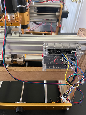
After the CNC Machine was reassembled I was focused on adding parts and components to the extended body frame, this included connecting the other microcontroller, stepper motor, and testing operation system. The images below show the x-axis and z-axis with the stepper motor mounted to the frame. The microcontroller was then connected to start a test run and make sure all components were working and running properly. The CNC Machine is continuously been modified and has been working day by day to have a fully operational model.
This week I updated the website and made adjustments recommended for the previous meeting. The website updated tab pages were the engineering requirements/specifications, success criteria, timeline table, and weekly presentation.
Team:
Discussed about the project in general and created an assembling procedure format for correction and future use.
Table Assembly Procedure
Step 1: Pre-Assembly Preparation
1.1. Gather all necessary materials and components, including two y-axis side solid wooden, two x-axis side aluminum sides, screws, nuts, bolts, and all the required tools.
1.2. Measured the correct dimensions mark and cut the wood and the aluminum to ensure smooth edges.
1.3. Drill all the necessary holes to attach stepper motors, lead screw, support rod, limit switch, and attachment bolt and nuts.
Step 2: Lay Out Components
2.1. Lay out all components on a clean, flat workspace, ensuring you have easy access to each part.
2.2. Arrange the wooden panels and aluminum profiles according to your assembly plan or design.
Step 3: Assemble the Wood


Week 18, Sept 5 - 12
Yohanes:
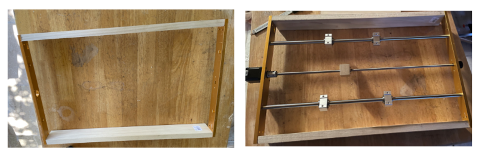
As I did more research and waited for machine parts to arrive I reassembled the CNC Machine and adjusted the body frame for the extension model to include the laser module. The y-axis linear movement was modified and the lead screw rod was mounted to complete the bottom frame. The figure below shows the completed bottom y-axis body frame.
Ramon:
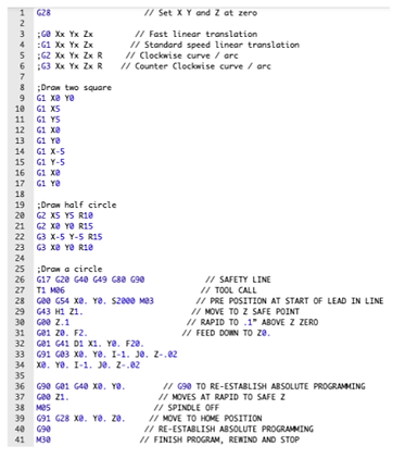
This week I edited the website and made some adjustments to the section on engineering requirements/specifications as well as some minor content on each tab section for the design project webpage. I focus on programming some simple gcodes that would help and be implemented on the CNC Machine. Using the software tool called "NCViewer" an open source under "GNU General Public License" I created two rectangular, half circles, and a full circle that can be programmed into our CNC Machine program system, as shown below.


TEAM:
This week has certainly been a learning experience for us.
1)Y-Axis Lead Screw Nut Compatibility:
Issue: We encountered an issue with the y-axis lead screw nut, as it was incompatible. After multiple attempts, we realized that the screw was metric, while the nut was in standard inches.
Solution: To resolve this problem, we have ordered a metric screw with a matching metric nut. The new arrived, tested it is compatible and working properly.
2) Spindle Z-Axis Missing Parts:
Issue: The 2nd spindle z-axis router holder initially arrived with a missing part. We contacted the seller, and they sent us a replacement. However, the replacement parts did not match the stainless-steel rod runner we had acquired. Instead of the original 10mm diameter rod, the part we received was 8mm in diameter. This mismatch caused instability, resulting in a wobbly and zigzag motion that would compromise the machine's performance.
Solution: To ensure compatibility, we have separately ordered a T10mm rod, and we anticipate its arrival on September 14.
3)The 1st Spindle Performance Issue:
Issue: Initially, the first spindle operated correctly during testing, but it has since developed issues such as jerking and making noise.
Solution: To address this problem, we conducted a thorough troubleshooting process and determined that all electrical components were functioning correctly. Voltage and current measurements were within acceptable ranges. However, we discovered inaccuracies in the machine's measurements, likely due to the high-speed movement. As a solution, we have decided to dismantle and reconstruct the machine with a focus on achieving the highest possible accuracy.
It is evident that we have been proactive in addressing these challenges. Ensuring precision in both components and measurements is crucial for the successful operation of our project. We are hopeful that with the arrival of the new parts and our meticulous adjustments, we will overcome these obstacles and achieve the desired accuracy and performance in our project.
Week 17, Aug 29th - Sept 4th
Team:
The CNC Machine is currently being extended which is by adding another frame to the existing model. The Laser module, stepper motors, and microcontroller will be attached. The project is undergoing modification and progress. The below image and video show an extended frame and benchwork as well as the first test cut of a simple square.


Week 16, Aug 22 - 28
Ramon:
The design phase table was updated with week by week of the detailed process for the project, it gives a brief description and a proposed timeline of the CNC Machine.
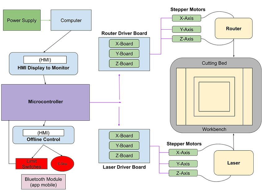
Also, for this week I made some adjustments to the block diagram that can be clearly understandable and how the CNC Machine components operate with the new redesign model. The project is currently going into some modification, while construction the system block diagram and flow chart will slightly be adjusted with project needs.

Yohanes:
I edit the Design Engineering Requirements based on the project needs. The levels were upgraded with specific components to make the CNC Machine operational and have an understanding requirements for the project. Based on the proposal presentation we made adjustments from "The Device Shall" and the Verifications/ Success Criteria shown in table below.
Also, this week started ahead of time and gathered writing documents for the Design Report. I started the report paper by adding the introduction, abstract, and product description overview.
Product Description Overview:
CNC (Computer Numerical Control) machines are renowned for their precision, repeatability, and consistency in performing various machining tasks. The ability to automate operations with CNC-controlled spindles ensures that each task is executed with a high degree of accuracy.
The proposed multifunction CNC machine offers two tasks with one setup. This machine's ability to perform two machine tasks in one setup significantly increases production efficiency. It eliminates the need to reset or reposition workpieces between tasks, reducing downtime.
The proposed machine has several significant advantages compared to similar CNC machines in the market:
Reduced Setup Time: By combining two machine tasks into a single process, the machine reduces setup time. This not only saves time but also minimizes the risk of errors associated with manual repositioning or realignment of workpieces.
Ease of Design Retention: The ability to retain computerized designs for later use simplifies the production process. It allows for easy replication of previous projects and ensures consistency in product quality.
Cost-Effective: Despite its multifunctionality and efficiency, the machine's cost remains reasonable. It offers a cost-effective solution for small businesses hobbyists, and entrepreneurs looking to improve their machining capabilities without a significant capital expenditure.
In summary, the multifunction CNC machine's ability to perform two tasks in one setup, reduce setup time, minimize wastage, and deliver high-quality products makes it a valuable asset for various industries. Its cost-effectiveness and versatility make it a compelling choice for businesses looking to enhance their production capabilities and overall efficiency.
Week 15, Aug 15 - 21
Ramon:
This week I focus on designing a basic Gcode to make the first cut with the CNC Machine using the router. The software program used in the below image to generate a square cut was "Universal Gcode Sender". The software is used to upload a design created with Gcode, it is then connected to the model via a USB connection to the CNC Machine microcontroller.

Yohanes:
The wiring, microcontroller, and power supply were attached to the back of the frame. It was the first step to construct the CNC Machine and upload software for test and cut run. Next was to add the stepper motor axis for the next phase of the project but it was critical to mount the microcontroller and power supply to be operational and load software.

Week 14, Aug 8 - 14
Ramon:
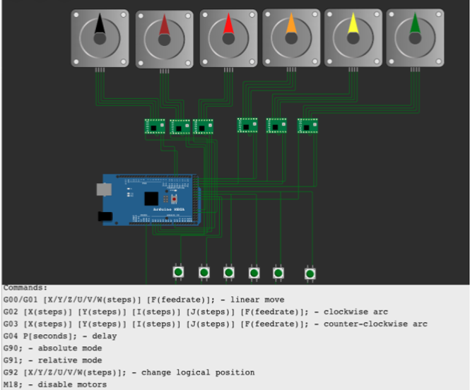
With the new redesign model, I worked on the software program and got in-depth with the microcontroller and stepper motors. The CNC Machine is controlled by an Arduino as the microcontroller, it also controls and calibrates the stepper motor's linear axis movement. There are 5 stepper motors that will be connected to the specific component such as the router and laser. To have a visual understanding I used an Arduino simulator called "Wokwi" and had a gasp on how stepper motors would operate before implementing it on the actual physical model. Below is an example of a 5-6 stepper motor and a simple basic GCode to move each axis.
Yohanes:
Focus on collecting and purchasing, collect, and gather the necessary components from Amazon, Skycraft, and Harbor Freight for your project. from Amazon, I bought: stepper motors, sensors, controllers, and cables.
Skycraft, I purchased aluminum sheet for table top, aluminum bar for stand, switches, hoses, conduit for wires. Also I gathered some leftover plywood, screws, zip ties and glues from my garage.
Week 13, Aug 1 - 7
Ramon:
New redesign CNC Machine to be discussed. This week Yohanes and I discussed a new idea for the project to make it more unique and different from other CNC machines on the market. Using the same concept design from the Senior Proposal we came up with a router and a laser engraver to be added to the project.
Team:
The team discussed and ensured we had a clear understanding on recommendations and suggestions from the panel and the professor, and we took several important steps to modify our project based on recommendations and suggestions from a panel and a professor.
We valued the Recommendations: It's crucial to have a solid grasp of the recommendations and suggestions provided by the panel and the professor before proceeding with project design. To ensure that we are aligned with their expectations we modified a unique and budgeted machine.
Uniqueness: to ensure our CNC machine design is unique compared to others in the market, we modified our design from a single-spindle CNC machine to a dual-spindle one. This modification is to response to some of the panels’ concerns. Based on our research, there is no dual spindle machine which costs $600. Dual-spindle machines is not only unique it is more versatile and capable of machining tow tasks in one setup, which confirms our machine is a multitasking device.
Cost Consideration: the modification made ensured that our modified design remains cost-effective and within the $600 budget constraints set by our design proposal project.
Overall, our team took a well-structured approach to developing to modify multifunction CNC machine project. By incorporating feedback, conducting thorough research, and considering cost-effectiveness.